Christmas Lights Extravaganza
I've been sitting on this one for a while now. I'm sure everybody's seen the video, but I've been meaning to do a technical writeup. In case you haven't seen the video and have no idea what I'm talking about: I made a computer controlled lights setup. You can watch it below:
Okay, now that we have that out of the way, follow the break for the technical goodies.
Layout
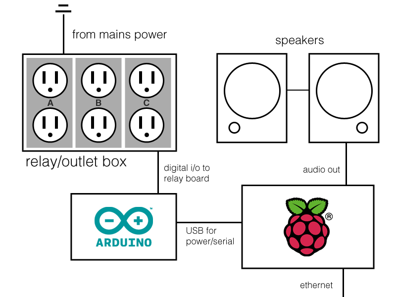
Certainly I mentioned it some time ago, but at the heart of this project is an Arduino Uno. Actually, there are two hearts in this case. The other one is a Raspberry Pi, the $35 micro computer. Both of these pieces perform very different roles, but before I delve into that, have a shoddily drawn "schematic" on how all the parts are connected:

Here's a quick rundown of each component and its use:
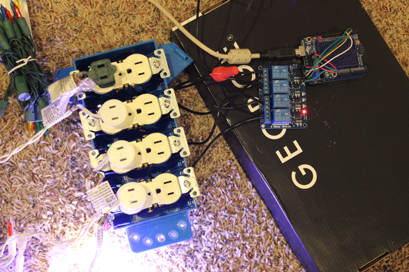
Relay/Outlet Box - This is a gang box that consists of four outlets all hooked up into a relay board (I used this one). This allows me four separate channels of light control for up to eight strings of lights. The channels in my setup are broken out into the lights on the tree, the star, and two strings of lights on either side of the tree.
Arduino - The Arduino in this case doesn't actually do much. It receives commands from the Raspberry Pi via serial communication and toggles the appropriate relay. It also takes input from the button on the proto shield and sends that back to the Pi.
Raspberry Pi - The Pi is what does most all of the heavy lifting. It plays the music and parses the sequence file to send the correct commands to the Arduino at the appropriate time. It'll also change display modes upon pressing a button on the Arduino. Pressing the button cycles through the following modes: play loaded light sequence, all on, all off.

That's the hardware side, let's move onto the softer side of things.
Sequencing

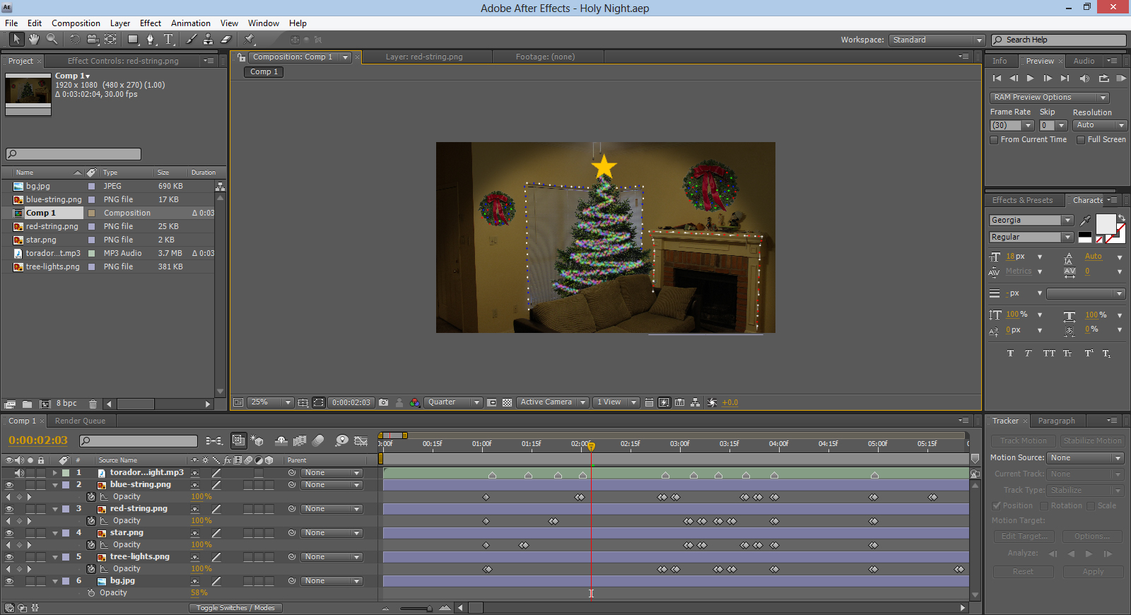
All of my sequencing was done in After Effects. I setup a basic scene with all my light channels (mapped to approximations of what they'd be in real life) and the song I was sequencing. I used the opacity property to set the on/off state of each string; 0 was off, non-0 on. Sadly, I forgot all about hold frames until I was nearly done, so I have a lot of side-by-side key frames keeping the previous state. The composition was set at a flat 30fps to make time coding easy later. Once I was done sequencing, I copied each layers key frames into a flat text file for compilation later.
Code
With the hardware and sequencing in place, only code remained. There are three programs used through out the process: one to compile together all the pasted sequences from After Effects into a nice JSON format, the program to parse said file and output data to the Arduino, and the program running on the Arduino itself. Note - there's not a lot of code, but too much to paste here. I've made the entire project available on GitHub.
Parsing After Effects Key Frame Data
This script was written in PHP because it's what I work with fastest. The keyframes code was slightly augmented to identify what string was what (String ID). It is then time coded and converted into a nice JSON format. The sequence can be found here and the converter program converts it to some nice JSON.
The Raspberry Pi's Side
This part was initially written in node.js, but I couldn't find a good library for playing music and keeping tabs on it's current position. So, I settled for Python and the PyGame library since both are installed by default in the Pi linux distro. The main loop of the script just sits around waiting for button input. The sequence loop parses the JSON file from above, waiting until the music hits a point that requires action. It then sends out the following byte for each command:
AAAABBBB
The upper four bits are the on/off state and the lower four are the string that the action is to be carried out for. It's pretty simple and keeps the throughput low.
The Arduino Side
As stated above, the Arduino side is very simple: it sits and waits for commands from the Pi or for the button to be pressed. When it receives one of the command bytes, it breaks it down into the two parts and sends HIGH or LOW for the correct pin taking into consideration the fact that I started on digital pin 4. The Arduino code can be found here.
So, that's pretty much everything in a nutshell. Overall, for a first attempt doing really anything like this, I'm quite pleased with the results. Next year, I'd like to get away from the relay board (it's loud as hell) and use MOSFET which would grant me the ability to do fades and not just on/off. Also, I'd like to expand beyond just four channels and perhaps throw in a RGB LED strip for extra fun.

